1. Basic configuration
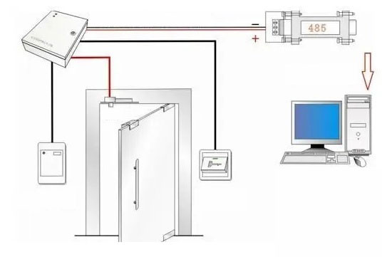
The configuration of the simplest non-networked Access Control system includes: an access control all-in-one machine, a 12V power supply, an exit button, and an electric lock. The configuration of the simplest networked access control system includes: an access control controller, a 12V power supply , an exit button, an electric lock, a card reader, and a 485 communication converter.
As the picture shows:
2. Recommended installation and debugging process
(1) Install the controller host, turn on the power, short-circuit the exit button, and observe the relay action and the status change of the relay unlock indicator.
(2) Connect the 485 communication, install the software, add the controller in the software, and pay attention to fill in the correct serial number.
(3) Open the debugging interface to observe the communication situation.
(4) Observe whether the communication is normal, use the software to open and close the door after communication, whether it is successful.
(5) Install a card reader and check whether the card swiping operation has a correct record.
(6) Add user, card issuance and authorization operations, download the card to the controller, and swipe the card to observe whether the record is normal.
(7) Install the connecting wire that is connected to the lock, and observe whether the record and the lock are normal after swiping the card.
(8) Install other auxiliary equipment such as buttons.
3. Construction wiring specifications and precautions of access control system
The line from the card reader to the controller: It is recommended to use an 8-core shielded multi-strand twisted pair network cable, and the data lines are twisted pairs. The longest can not exceed 100 meters. The shield wire is connected to the GND of the controller.
Wire from the button to the controller: It is recommended to use a two-core wire with a wire diameter of more than 0.3 square millimeters.
The cable from the electric lock to the controller: It is recommended to use a two-core power cable with a diameter of more than 1.0 square millimeters. If it exceeds 50 meters, consider using a thicker wire or multiple strands in parallel, or increase the output voltage to about 14V through the fine-tuning button of the power supply. The longest should not exceed 100 meters, generally controlled within 60 meters.
The wire from the door sensor to the controller: it is recommended to choose two-core wire, the wire diameter is more than 0.3 square millimeters. If you don't need to know the switch status of the door online or do not need the alarm function of the door not closed for a long time and illegal intrusion alarm function, the door magnetic wire can be disconnected. .
Between the controller and the controller: and the cable from the controller to the converter, it is recommended to use an 8-core shielded twisted pair network cable. The length of the 485 bus can theoretically reach 1200 meters. It is recommended that it should not exceed 800 meters according to the number of controllers or the complexity of the communication environment. If it exceeds, use 485HUB or repeater to improve the communication environment.
Contact: Adam
Phone: +86 18205991243
E-mail: sale1@rfid-life.com
Add: No.987,Innovation Park,Huli District,Xiamen,China