
The working voltage is DC 5V, 12V, 24V optional, the default is DC 12V
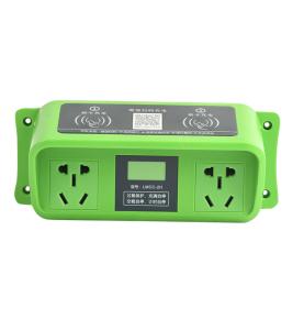
The product comes with several commonly used functions, which can control solenoid valves, water pumps, motors, light strips, etc. to operate freely; if you need other functions; you can program and customize customer needs: simple and free;
Input voltage: DC 5/12/24V optional; default 12V
Output power: can control DC or AC loads within 5A
Time range: adjustable at any time from 0.1 second to 999 minutes
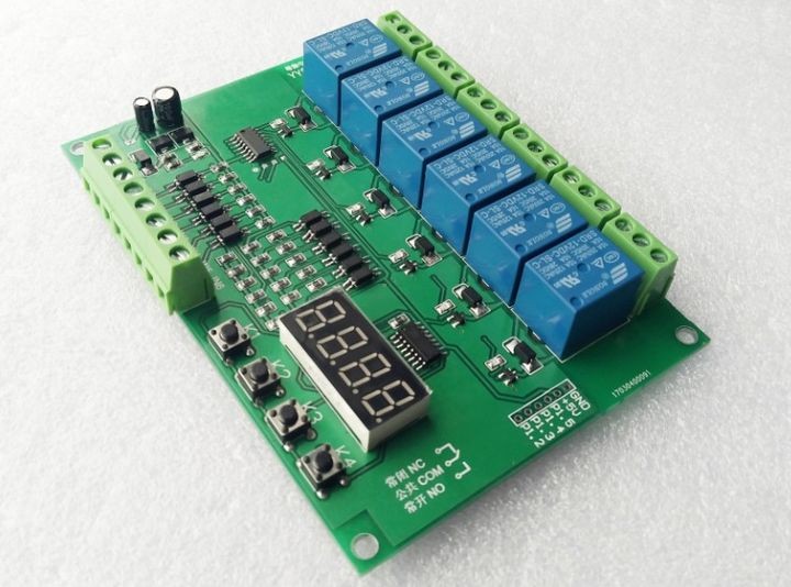
Wiring port description:
1. DC+: Input the positive pole of the DC power supply
2. DC-: Negative pole of input DC power supply
3. IN1~IN6: signal input terminal (NPN, negative trigger)
4. NO: The relay is normally open interface, the relay is suspended before the pull-in, and shorted with COM after the pull-in
5. COM: Relay public interface
6. NC: The normally closed interface of the relay, the relay is shorted with COM before the pull-in, and it is suspended after the pull-in
6: Function list:
P-11: Self-locking: give signal 1; relay 1 starts; give signal 1 again; relay 1 stops (six channels are independent of each other; they can be triggered separately)
P-12: Interlock: give signal 1; relay 1 starts, other relays stop; give signal 2; relay 2 starts, other relays stop; (six-way interlock; only one relay is working at the same time)
P-13: Jog: Give signal 1, relay 1 starts; signal 1 disappears, relay 1 stops; (six channels are independent of each other; they can be triggered separately)
P-14: Give signal 1; start relay 1; delay off; give signal 2; start relay 2; delay off; (6 different delay times can be set separately, only one relay is working at the same time) P -21: After power on; relay delay start (6 different delay times can be set separately)
P-22: After power on; the relay delays to output a switch signal (10ms) (6 different delay times can be set separately)
P-23: Give signal 1; delay start of relay (6 different delay times can be set respectively)
P-24: Give signal 1; the relay delays to output a switch signal (10ms) (6 different delay times can be set separately)
7: Button setting instructions: "———" is displayed when the power is on, indicating that it has entered the standby state;
Press K1 for the first time, (it takes more than 1 second to be effective, to prevent false triggering) Display: P -11: K2K3 adjusts the main mode, K4 adjusts the function
Press K1 for the second time, the screen displays: 1 001: K2 and K3 adjust the first time, K4 adjusts the decimal point (time unit)
Press K1 for the third time, the screen displays: 2 001: K2 and K3 adjust the second time,
Press K1 for the fourth time, the screen displays: 3 001: K2 and K3 adjust the first time,
Press K1 for the fifth time, the screen displays: 4 001: K2 and K3 adjust the second time,
Press K1 for the sixth time, the screen displays: 5 001: K2 and K3 adjust the first time,
Press K1 for the seventh time, the screen displays: 6 001: K2 and K3 adjust the second time,
Press K1 for the eighth time, display “— — — —” means entering standby state
8: Decimal point time unit Description:
XX.X decimal point in ten, timing range: 0.1 seconds ~ 99.9 seconds
XXX has no decimal point, timing range: 1 second to 999 seconds
XXX. The decimal point is in ones place, timing range: 1 minute ~ 999 minutes
Contact: Adam
Phone: +86 18205991243
E-mail: sale1@rfid-life.com
Add: No.987,Innovation Park,Huli District,Xiamen,China
 Adam
Adam