
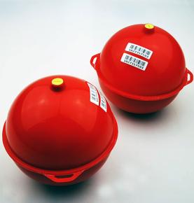
ED2000 Underground Electronic Marker have two models(ID or Non ID). It consists of a sealed shell containing a passive antenna - a low-frequency resonance circuit tuned to a certain frequency. The ID version integrates an ID chip. Depending on the resonant frequency and the color, the ED2000 are used to mark a wide range of underground facilities, such as telecommunication lines, power supply networks, cable television networks, water supply pipelines, wastewater networks, oil and gas pipelines, and so on.
It is widely used in the positioning and identification of pipe networks, pipelines, and pipe corridors in gas, electricity, water conservancy, communications and other industries. It can be used to bury electronic markers at turning points, tee openings, etc. to mark and bury electronic signs during the pipeline laying process. The information that the device can carry includes: burial point characteristics, pipe material category and grade, pipe diameter, design pressure, pipeline burial depth, burial time and other information.
Working principle of underground electronic tags
The underground gas pipeline electronic identification system activates the underground electronic tag by sending an electromagnetic wave signal of a specific frequency through the detector. The signal is reflected back to the detector. Based on the signal strength, the detector can detect the precise location (latitude and longitude) and depth of the electronic tag.
√Packaging material: high density polyethylene shell
√Waterproof, anti-corrosion and durable
Underground electronic markers | Electronic markers do not have an ID number. The buried longitude and latitude coordinate information is determined by the detector, and a unique ID number is assigned in the GIS geographical information management system, bound to the longitude and latitude coordinate information, and attached to the relevant Description. It is composed of a sealed and waterproof high-density polyethylene shell and a passive antenna inside. It has a built-in resonant circuit with a specific frequency. The effective service life is not less than 50 years, and the maximum detectable depth is 1.8 meters.
Underground electronic tags need to be used in conjunction with underground pipeline detectors to form an underground gas pipeline electronic identification system. The detector sends an electromagnetic wave signal of a specific frequency to activate the underground electronic tag. The signal is reflected back to the detector. According to the signal strength, the detector can detect The precise location (latitude and longitude) and depth of the electronic tag.
Functions:
1. The detector sends signals of a certain frequency intermittently
2. Underground electronic tags with the same resonant frequency absorb and Store signal energy.
3. After the detector sends a signal for a short period of time, it stops sending and enters the signal receiving mode.
4. When the detector stops sending signals, the underground electronic tag will release the stored energy and reflect it back to the detector, so the underground electronic tag does not require a battery to work.
5. The detector detects the returned signal strength to determine the specific location of the underground electronic tag.
6. The signal is strongest when the detector is closest to the underground electronic tag, that is, directly above the underground electronic tag.
Features:
(1) It is waterproof, antimagnetic, high temperature resistant and not affected by the environment.
(2) It adopts passive and contact-free operation and is easy to use. It only needs to be placed in the electromagnetic field formed by the detector to accurately read data, reducing or even eliminating the efficiency reduction and error correction costs caused by manual intervention in data collection.
(3) Reading data is fast and over a long distance. It can read the data stored inside the tag and associate it with the information in the background management system through the mobile Internet to display the tag information in real time.
(4) Reading does not rely on visible light, so visual visibility is not required and can be used in harsh environments where barcode and nameplate technology cannot adapt.
(5) It has a confidentiality function for information data, so that the data can only be read by a dedicated reader.
APPLICATIONS
ED2000 can be installed at a certain interval, or at the turning of changing trend and at some event points, such as connection points, valves, well covers, T-shaped branches, etc. According to the project importance and project budget, the instralling density can vary from several meters to tens of meters, usually 10-20 meters.
· Pipeline path
· Nonmetallic pipe
· Various valves
· Metering meter
· Various crossing points
· Tee · Depth change
· Pressure reducing device
· Cathodic protection
· Pressure control point
· Embedded reserved port
· Various elbows
· Pipe diameter change
· Water well · Cover
· Maintenance point
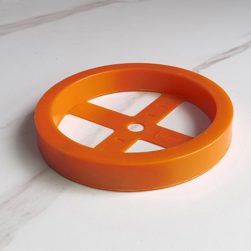
RFID gas pipeline positioning disc marker
RFID power cable pipeline positioning disc marker
RFID water supply pipe positioning disc marker
RFID drainage pipe positioning disc marker
RFID communication optical cable pipeline positioning disc marker
RFID municipal universal disc marker gas pipeline positioning disc marker
RFID power cable pipeline positioning disc marker
RFID water supply pipe positioning disc marker
RFID drainage pipe positioning disc marker
RFID communication optical cable pipeline positioning disc marker
RFID Municipal Universal Disk Marker
FEATURES
3.1. Physical Characteristics
· Shell: ABS
· weight:220g±10%
· Case diameter - 8.4in (213mm)
· Case height - 1.2in (3.1cm)
· Melt index: 1.8g/10min (200 ℃ / 5kg)
· Rockwell hardness: R-116
· Softening point: 105 ℃
3.2. Environmental characteristics
· Working temperature: - 20 ℃ - 50 ℃
· Storage temperature: - 20 ℃ - 70 ℃
· Drop test: it can withstand the drop from 10 feet (about 3 meters) to the concrete floor
· Waterproof and dustproof: IP68
· Compression capacity: after bearing 10kN axial pressure (uniform pressure), the product has no permanent damage, crack and leakage, and its electronic function has no damage
3.3. Electrical Characteristics
· Maximum placement depth - up to 6.5ft (2.0m)
· Minimum distance from the metal facility to marker - 4in (10cm)
· Global Unique ID code(ID Version): 10 digits
· Compatible locator:
Non ID version: ED8000 or 3M Dynatel EMS Locator
ID version: ED8000
· Frequency (customizable):
Power 169.8khz
Water 145.7 kHz
Sanitary 121.6 kHz
Telecom 101.4 kHz
Gas 83 kHz
Cable TV 77 kHz
General 66.35 kHz
Installing The Marker
· Place the marker on nonmetal cable
· Place a minimum of 4 inches (10 cm) of fill dirt over the cable with metal (including shielded cable, Coaxial cable etc.).
· Sand should be used to cover the marker before covering soil. It can give better protection to marker


Scope of use:
1. Directly buried non-metallic gas, electricity, water supply, communications, sewage and other pipelines and facilities must use electronic identification systems;
2. For directly buried metal gas, electricity, water supply, communications, sewage and other pipelines and facilities, electronic markers are selected according to the complexity of the lines;
3. All types of valves for underground gas, electricity, water supply, communications, sewage and other pipelines;
4. All manhole covers that are not visible or may be buried by municipal authorities (roads, greening);
5. All underground gas, electricity, water supply, communications, sewage and other pipelines are not in the turns of human wells;
6. Branch points and joints of all underground gas, electricity, water supply, communications, sewage and other pipelines, such as tees and reducing joints;
7. The intersection of all underground gas, electricity, water supply, communications, sewage and other pipelines and other underground facilities;
8. Gas, electricity, water supply, communications, sewage and other pipelines cross the two ends of roads, rivers, buildings, walls or other public relations facilities, and can be the two ends of gas pipeline protection pipes;
9. When the depth of gas, electricity, water supply, communications, sewage and other pipelines changes by more than 0.5 meters, the location is high and low;
10. All pre-buried pipe ends for gas, electricity, water supply, communications, sewage, etc.;
11. Both ends of underground pipelines such as gas, electricity, water supply, communications, sewage, etc. laid by trenchless technology;
12. Repaired underground gas, electricity, water supply, communications, sewage and other pipelines or joints (used to identify maintenance information);
13. All other important underground gas, electricity, water supply, communications, sewage and other facilities marked on the File drawings;
14. All places that operators think need to be marked and positioned
Installation plan
1. Before placing electronic signs, first evaluate whether connection binding is necessary. If necessary, use a tie to pass through the electronic marking hole and ensure a reliable connection, and then manually backfill both sides of the pipe with fine sand to the bottom of the electronic marker to ensure that the marking will no longer be deflected.
2. If the object to be marked is metal, it is recommended that the marker be spaced at least 10 cm away from it and filled with soil in between.
3. Backfill 15 cm above the logo to fix the position of the logo.
4. Backfill until it is level with the ground surface.
Contact: Adam
Phone: +86 18205991243
E-mail: sale1@rfid-life.com
Add: No.987,Innovation Park,Huli District,Xiamen,China

 Adam
Adam